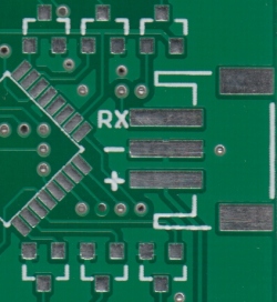
Go through the circuit board and record the values of all the parts that have values. On a schematic you will also see a electrical components symbol next to it will have a identification number next to its abbreviation ie.
In circuit diagrams there are many electrical symbols that are used to represent different electrical components and devices.

How to read a circuit board. List in a column the labels of all the parts and their values found on the board. The abbreviation for a resistor r followed by a number to identify it on a pcb r102. For most symbols polarity is included in the symbol.
To find out the polarity of the physical part a general rule of thumb is to look for which metal lead wire on the part is longer. You will see the symbol for a resistor. Recognizing circuit diagrams symbols once you know the language or terms of circuit diagrams you are half way of being able to reading them.
In the the photos below you will find a guide to distinguishing polarity for various symbols. Next to the symbol you will also see its value 2 2k. This means you have to attach it in a certain way.
Here is an overview of the most used symbols in circuit diagrams. Some components to a circuit board are polarized meaning one side is positive and the other is negative. Many components use colored bands to record their values instead of numbers.
This is the side.